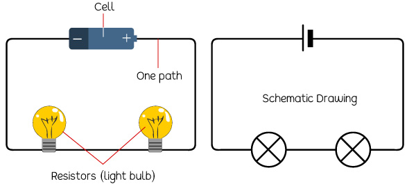
A series circuit is one that has more than one resistor but only one path through which the electricity (electrons) flows. From one end of the cell (battery), the electrons move along one line with no branches, through the resistors, to the other end of the cell. All the components in a series circuit are connected end-to-end.
A resistor in a circuit is anything that uses some of the power from the cell. In the example below, the resistors are the bulbs. In a series circuit, the components are arranged in a line, one after the other.
Take a look at the diagram below:
The schematic drawing is a better way to draw a series circuit.
Each time there is damage (break) in any one of the resistors, the entire circuit will not function. For example, if one light bulb goes out, all the other lights will go off because the electricity path in the broken bulb is cut-off.
Do you put Christmas lights on the trees at home during Christmas? If the lights are in a series circuit, one burned-out bulb will keep all the lights off. That is one disadvantage of series circuits. One advantage though is that you will always know if there is a break in a series circuit.
If there are many bulbs in a circuit with a battery (cell), the light will likely be dimmer. It is because many resistors are acting on the same voltage of power from the battery.
Now let us take a look at Parallel Circuits.